http://tuxgraphics.org/electronics
|
Content:
By Guido Socher |
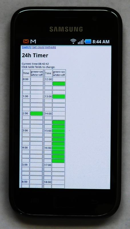
24h timer with web interface![[Illustration]](../../common/images2/article11022/title.jpg)
Abstract:
Timers are present everywhere. Many industrial control systems
needs timers. Your heating system might have
one where you can define when to change between day and night
profile. Sometimes you might just want a simple timers to
switch on/off the lights of the Christmas decoration.
|
2011-03-19, generated by tuxgrparser version 2.57